
Views: 0 Author: Site Editor Publish Time: 2026-09-09 Origin: Site


Decelerating moving loads safely is critical for maximizing machine throughput, preventing structural fatigue, and eliminating unplanned downtime. In high-speed manufacturing environments, you must control kinetic energy perfectly. Proper sizing is a measurable science. Engineers must treat it as a foundational step. Guessing or relying on trial-and-error for shock absorber sizing leads to severe problems. First, undersizing causes catastrophic equipment failure. The moving mass destroys the damper upon impact. Second, oversizing demands unnecessary capital expenditure and creates harsh impact spikes. You damage the very machine frame you want to protect. We provide a rigorous, physics-based framework here. You will learn how to calculate load requirements accurately. Then, we help you shortlist the correct industrial shock absorber for high-stakes automation and heavy machinery. We remove the guesswork entirely. By applying these specific mathematical steps, you ensure optimal deceleration, smooth operation, and long-lasting production lines.
Engineering and procurement teams must get deceleration parameters right before issuing a purchase order. In fast-paced industrial environments, the stakes remain incredibly high. When you incorrectly size a damper, you introduce massive operational risks to your machinery. Teams often underestimate how much damage a moving mass can inflict when it stops abruptly. You must understand the physics of impact to mitigate these risks effectively.
Undersizing creates immediate and obvious failures. When a unit lacks the necessary energy capacity, bottoming out occurs. The shock absorber piston reaches the end of its stroke before fully dissipating the load's energy. This remaining energy transfers directly into the machine frame. You will see accelerated wear on bearings, rails, and structural joints. Furthermore, bottoming out frequently voids manufacturer warranties because it constitutes improper use of the component. The internal pressure spikes so high it destroys the internal seals.
Oversizing introduces a different set of destructive problems. Many engineers assume a larger unit provides a safer buffer. However, an oversized damper requires too much force to compress. It results in "hard stopping." The shock acts like a solid block of steel. When the load hits it, the mass bounces off or experiences destructive G-forces. These forces rattle sensitive electronics, misalign sensors, and damage the product you are manufacturing.
Your ultimate success criteria rely on achieving linear deceleration. In a perfect system, you create a constant reaction force. The load comes to a smooth, controlled rest while utilizing the entire available stroke length. This maximizes energy absorption without putting undue stress on any single part of the machine structure.
You cannot select a proper deceleration device without specific data points. We define these non-negotiable inputs below. Whether you calculate them manually or use a vendor sizing calculator, this baseline information drives the entire process.
Mass / Effective Weight ($W$ or $m$): You need the actual weight of the object being stopped. Measure this in pounds (lbs) or kilograms (kg). Include the weight of the payload and any moving structural components holding that payload. Accuracy here forms the foundation of your energy calculations.
Impact Velocity ($v$): This represents the speed of the mass at the exact moment it hits the industrial shock absorber damper. Do not use the average speed of the process. You must find the terminal velocity right before impact. Emphasize this metric heavily. Velocity is squared in kinetic energy calculations. It remains the most critical variable. A slight miscalculation in speed exponentially increases the actual energy your system must handle.
Propelling Force ($F_D$): Many loads do not just coast into the damper. Additional drive forces often push the load during the deceleration phase. Common examples include pneumatic cylinders, AC motors, or gravity. If a motor remains powered while the load hits the shock, you must account for this extra pushing force. Ignoring it guarantees undersizing.
Cycle Rate ($C$): You measure this in impacts per hour. The cycle rate proves critical for determining the thermal capacity of the unit. Every time a shock absorbs energy, it converts that kinetic energy into heat. If the impacts happen too frequently, the unit cannot dissipate the heat fast enough. This leads to overheating and rapid seal failure.
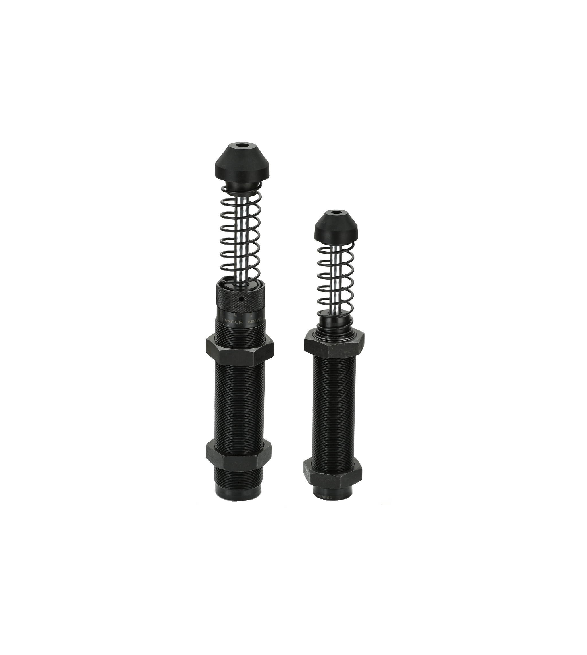
Deceleration is a strict mathematical process. You must calculate the total energy the system generates. We break this down into four sequential steps. Follow them closely to ensure reliable sizing for your automation line.
As a best practice for trustworthiness and safety, we advise engineers to add a standard 15-20% safety margin to theoretical calculations. Real-world friction varies over time. Payload shifts happen. Pneumatic pressures fluctuate. A safety margin accounts for these inevitable factory floor realities without crossing into the dangerous territory of oversizing.
Once you calculate your total energy, you must select the physical architecture of the damper. Different environments and applications demand specific construction styles.
We first look at fixed versus adjustable units. Fixed, or self-compensating, shocks are best for high-volume OEM equipment with predictable, unchanging loads. They are tamper-proof. Once installed, operators cannot alter the settings. Conversely, an adjustable industrial shock absorber is ideal for testing environments or variable payload automation lines. If exact velocities are difficult to pre-calculate, an adjustable dial provides tuning flexibility during commissioning.
Next, you evaluate heavy duty versus standard profiles. You should evaluate a heavy duty industrial shock absorber for crane bumpers, foundry equipment, or high-mass/low-velocity applications. These robust units feature oversized piston diameters and reinforced outer bodies to handle massive forces without buckling.
Finally, consider hydraulic versus pneumatic operation. Standard hydraulic deceleration relies on fluid metering. Hydraulics offer higher energy absorption in smaller physical footprints. They dominate heavy manufacturing. In contrast, a pneumatic shock absorber uses air cushions. These are highly preferred in cleanrooms, semiconductor manufacturing, or food-grade applications. They eliminate the risk of hydraulic fluid leaks contaminating the product.
| Category | Primary Use Case | Key Benefit | Common Limitation |
|---|---|---|---|
| Self-Compensating (Fixed) | Dedicated OEM machines with known loads | Tamper-proof reliability | Cannot adapt to drastically changed payloads |
| Adjustable | Testing rigs and variable automation lines | High tuning flexibility on site | Operators might incorrectly alter settings |
| Heavy Duty | Cranes, foundries, steel mills | Handles extreme mass impacts safely | Larger physical footprint required |
| Pneumatic | Cleanrooms and food processing | Zero risk of fluid contamination | Lower maximum energy capacity than hydraulics |
Selecting the right damper on paper only solves half the problem. You must mitigate mechanical and environmental risks during actual installation. Ignoring these constraints leads to rapid component destruction.
Side load and alignment pose the biggest mechanical threats. Industrial shocks are strictly designed for axial loads. They expect the mass to hit perfectly straight down the center line of the piston rod. Any impact angle greater than 1–3 degrees causes severe side loading. This uneven pressure scrapes the internal bearings and bends the piston rod. If your application involves rotational impact or angled strikes, you must install a side-load adapter or a clevis mount. These accessories guide the force back into a linear path.
Environmental extremes alter performance drastically. Standard units operate well at room temperature. Extreme cold thickens standard hydraulic fluid, causing the shock to become too rigid. This leads to hard stopping. Extreme heat degrades standard polyurethane seals, causing fluid leaks and loss of pressure. If your facility experiences these extremes, outline requirements for specialized silicone fluids or high-temperature Viton seals. These upgrades maintain consistent viscosity and seal integrity under harsh conditions.
Mounting integrity is your final mechanical constraint. You must evaluate structural rigidity carefully. The machine frame must withstand the peak reaction force generated by the shock absorber without flexing. If the mounting plate bends during impact, you lose the linear deceleration profile. Reinforce the mounting brackets with heavy-gauge steel and ensure the threads are fully engaged to handle the violent energy transfer.
Choosing the right partner matters as much as doing the math. You must validate vendor data rigorously. When reviewing product catalogs, pay close attention to stroke charts and effective weight graphs. These tools show how a specific unit performs across different velocities. Do not just look at the maximum energy rating. Ensure you read the thermal capacity ratings to verify the unit can handle your specific impacts per hour ($E_4$).
Evaluate availability and standard catalogs versus custom units. Commercial off-the-shelf (COTS) items typically have short lead times. They offer quick replacements when a machine goes down. Custom-orificed units provide perfect linear deceleration for unique loads, but they carry longer lead times. Weigh the need for absolute precision against your facility's maintenance schedules.
Prioritize manufacturers who offer robust engineering support. The best vendors provide proprietary sizing software to back up your manual calculations. They offer downloadable CAD models for seamless integration into your machine designs. Look for companies that provide application engineering reviews. Having an expert validate your in-house calculations prevents expensive mistakes on the factory floor.
Successful load deceleration is a strict math equation, not a guessing game. By capturing the correct data and running it through standardized energy formulas, you protect your machinery from destructive forces. We walked through the critical transition from calculating Total Energy ($E_3$) to selecting the right mechanical architecture, whether you need a fixed unit or an adjustable one.
To move forward successfully, apply these core steps to your next project:
A: Dashpots provide velocity control (damping) throughout a stroke and resist motion in both directions, whereas shock absorbers are specifically designed to safely decelerate and stop a moving mass at the end of its travel.
A: Look for fluid leakage around the rod seal, a load that "bounces" upon impact (loss of damping), or the piston failing to return to its fully extended position.
A: Yes, they are highly versatile for permanent installations, provided the adjustment dial is locked down securely after commissioning to prevent accidental tampering by machine operators.
A: Overheating occurs when the "Total Energy per Hour" ($E_4$) exceeds the unit's thermal dissipation capacity. This requires upgrading to a larger body size or adding external cooling options.

