
Views: 0 Author: Site Editor Publish Time: 2026-09-30 Origin: Site


Modern production lines rarely handle a single, uniform payload in real-world operations. Instead, variable loads introduce fluctuating kinetic energy levels across operating cycles. Fixed-damping components simply cannot absorb these erratic forces efficiently, leaving machinery highly vulnerable. Improper tuning carries heavy consequences for your entire manufacturing floor. Equipment fatigue accelerates quickly, cycle times increase unnecessarily, and destructive "bottoming out" leads to premature seal failure. Unchecked impact forces will ultimately destroy expensive structural frames over time.
This guide provides a standardized, engineering-backed process for establishing safe, effective deceleration profiles. You will learn exactly how to tune an adjustable shock absorber for optimal performance. We will walk you through achieving true linear deceleration across varying payload weights and impact velocities. Mastering this process protects your equipment and optimizes your daily output.
Unpredictable load changes cause massive headaches in modern manufacturing. You might handle different product SKUs on a single conveyor line. These variations create erratic deceleration profiles across your workflow. One minute you process lightweight plastics, and the next you handle heavy metal components. Fixed damping units simply cannot adapt to these rapid shifts.
Using mismatched fixed shocks leads to severe operational problems. An under-damped setup causes hard, destructive impacts. The load slams into the end stop violently. Conversely, an over-damped configuration creates jarring bounce-backs. The payload hits a "wall" of fluid resistance. Both scenarios result in unplanned downtime and high replacement frequency. Operators face constant maintenance delays. Over time, these shock waves travel through the machine frame. They loosen fasteners and compromise weld joints. You end up repairing structural damage rather than just replacing a simple seal.
You can solve this by implementing correct hardware. A correctly specified and tuned industrial shock absorber yields a flat, linear deceleration curve. Linear deceleration means the stopping force remains constant throughout the entire stroke. This smooth process maximizes cycle speeds. It also fundamentally protects your machine's structural integrity. Production managers no longer have to sacrifice speed for equipment safety. You achieve higher throughput and a much longer machinery lifespan.
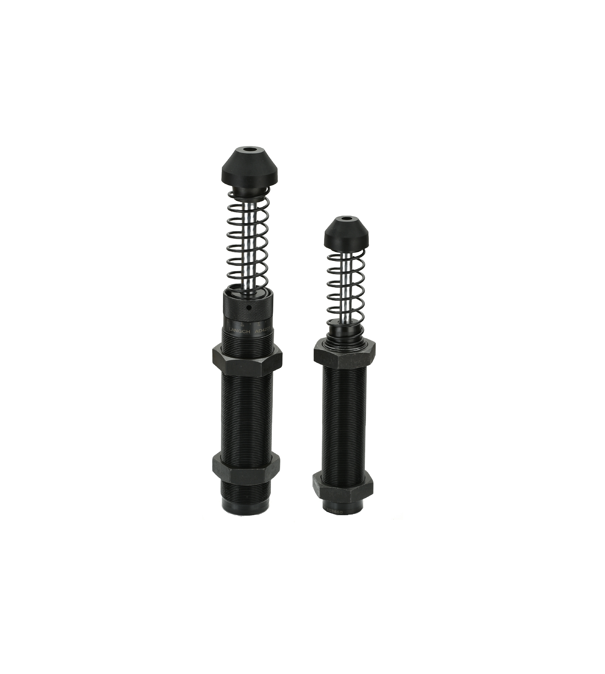
We will now break down the precise tuning methodology. Follow these phases carefully to ensure a safe, optimal setup across varying loads.
Always set the adjustment dial to "0" before introducing any load. This position represents maximum damping or the stiffest possible setting. Why is this critical? Never start at the softest setting. An unexpected heavy load will instantly bottom out. This violent impact damages the internal accumulator. It can also shear the piston head entirely. Starting closed manages your physical risk safely.
Begin by cycling the machine utilizing the heaviest expected payload. Run this test at your standard operating velocity. Carefully observe the deceleration profile. The load might stop abruptly. If the stroke is not fully utilized, the system is over-damped. You must incrementally open the dial. Move the dial to position 1 or 2.
Continue cycling and adjusting the dial. You want the load to utilize the full stroke of the industrial shock absorber damper. The moving mass should stop smoothly just before hitting the physical end of the stroke. Proper tuning dissipates energy as heat evenly across the entire cylinder length.
You must now validate the opposite end of your spectrum. Run the machine using the lightest expected payload. Watch the stroke engagement closely. Verify the lighter load still achieves full stroke. It must not bounce back upon impact. It also must not stop prematurely halfway through the cylinder. If it bounces, your setting remains too stiff. Finding the optimal sweet spot accommodates both extremes safely without operator intervention.
Engineers frequently debate between adjustable and self-compensating technologies. Your choice dictates your operational flexibility and ongoing maintenance requirements. Let's compare the two options objectively.
Adjustable units offer specific advantages for controlled environments. They work best for operations where load changes occur infrequently. For example, you might change tooling once per shift. They also excel when engineers require fine-tuned control over the deceleration profile. A high-quality adjustable industrial shock absorber gives technicians granular command over stopping parameters. However, these units have notable trade-offs. They require manual intervention during changeovers. This reliance makes them vulnerable to operator error. An untrained worker might leave the dial on an incorrect setting.
Self-compensating units operate differently. They feature multiple internal orifices designed to adapt dynamically. They are best for high-speed automated environments. Use them when constant, unpredictable weight variations happen on every single cycle. The internal fluid bypasses orifices based purely on the load's impact velocity. The main trade-off involves a higher upfront purchase cost. You also lose granular control for highly specific edge cases.
You must evaluate your maintenance workload objectively. Compare the labor hours spent on manual tuning against the premium price of self-compensating units. Calculate the risk of human error causing machine damage. If manual adjustments create production bottlenecks, automation makes better sense.
Below is a straightforward comparison guide to assist your hardware selection process.
Shock Absorber Technology Comparison
| Feature | Adjustable Units | Self-Compensating Units |
|---|---|---|
| Load Variability | Infrequent, batch-based changes | Constant, cycle-to-cycle changes |
| Tuning Control | Granular, manual precision | Automatic, predefined ranges |
| Maintenance Labor | Requires active operator intervention | Set-and-forget operation |
| Risk of Operator Error | Moderate to High (incorrect dial settings) | Low (no external dials) |
Upgrading your motion control components requires strict attention to detail. You must evaluate several engineering parameters before purchasing new hardware. Guesswork will result in premature component failure.
Even experienced technicians make tuning mistakes. You can avoid costly downtime by recognizing these common implementation risks early.
Many teams fail to document baseline settings. Someone might accidentally bump the dial during routine maintenance. An untrained operator might alter it thinking they are fixing a jam. The machine then risks catastrophic impact damage. Always record the optimal dial position in your maintenance logs explicitly.
Perfect damping adjustments cannot fix poor mechanical alignment. Tuning dials only control internal fluid flow. Side loads exceeding 3-5 degrees will cause severe uneven seal wear. The piston rod scrapes against the inner bearing. This friction leads to inevitable fluid leaks regardless of perfect damping adjustments. You must square and align your mounting brackets first.
Never attempt to force the adjustment dial while the shock is actively compressed. The internal chamber remains under immense hydraulic pressure during the stroke. Forcing the dial can strip the internal metering mechanisms. This ruins the adjustment pin permanently. Make all dial adjustments only while the rod is fully extended and unloaded.
Do not use deceleration hardware to hide poorly configured air systems. Relying heavily on external dampers to compensate for improperly tuned cylinders is a major mistake. Operating a pneumatic shock absorber or drive cylinder without basic air-flow controls wastes energy. Fix your pneumatic exhaust metering first, then tune the hydraulic absorber for final deceleration.
Proper deceleration tuning requires a strict balance between mathematical sizing and empirical physical tuning. You cannot rely on guesswork when handling expensive production equipment. Variable loads demand uncompromising equipment reliability. Proper tuning effectively bridges the gap between raw hardware capability and daily operational efficiency. By following the "start closed" methodology, you protect internal seals and structural frames effortlessly.
Take time to audit your current deceleration hardware today. Review your maintenance logs for frequent end-stop failures or fluid leaks. Audit your current failure rates on deceleration components this week. Document the dial settings across your primary production lines carefully. If manual tuning is creating bottlenecks, take action immediately. Prompt your engineering team to consult with a motion control specialist. They can help you evaluate self-compensating or heavy-duty alternatives for your most demanding applications.
A: Over-damped systems cause the load to abruptly decelerate at the beginning of the stroke. This spikes the reaction forces transferred to your machine frame. Under-damped systems offer too little initial resistance. This causes a loud, damaging metal-to-metal impact at the end of the stroke because kinetic energy was not fully absorbed.
A: Air cushions act like mechanical springs and often cause severe bounce-back. They do not dissipate energy efficiently. Hydraulic units convert kinetic energy into heat for true linear deceleration. This fundamental difference makes hydraulic units vastly superior for handling variable heavy loads smoothly.
A: Extreme load variations require specialized approaches. You must evaluate dual-shock setups or implement mechanical staging to handle the mass. Alternatively, upgrade to a custom-orificed self-compensating unit. These specialized components are designed specifically for extreme effective weight parameters and high-ratio load fluctuations.

