
Views: 0 Author: Site Editor Publish Time: 2026-09-16 Origin: Site


In high-speed automated manufacturing, unmanaged kinetic energy leads to machine wear, excess noise, and catastrophic mechanical failure. When heavy payloads slam into mechanical stops without proper damping, the resulting forces destroy expensive components in milliseconds. While fixed dampers work well for predictable, static parameters, variable payloads and changing operating speeds require a much more adaptable solution.
Engineers cannot rely on guesswork when protecting delicate robotic arms or rapid-cycle pneumatic actuators. A shift in product weight or line speed can easily overwhelm a standard buffer. This guide breaks down the internal mechanics of an Industrial Shock Absorber. We explore how adjustable models control deceleration and the exact evaluation criteria engineers should use when shortlisting damping systems for modern automation equipment.
To understand how deceleration works, we first need to look at the core physics involved. Many older machine designs rely on basic coil springs or thick rubber bumpers to cushion impacts. These crude devices do not absorb energy. They simply store it temporarily and rebound it back into the system. This rebound creates damaging secondary vibrations throughout the machine frame. By contrast, a true industrial shock absorber damper absorbs the kinetic energy of a moving load and forces it to dissipate safely into the surrounding atmosphere as heat. The process transforms a destructive mechanical shock into a controlled thermal exchange.
The internal architecture achieves this energy conversion through a few highly precise components. When you dissect a standard unit, you find four main elements working in unison:
As the piston drives into the pressure tube, it forces the oil through the metering orifices. This fluid restriction generates resisting force. The magic of linear deceleration lies in how engineers arrange these orifices. Standard dashpots provide high resistance at the start of the stroke, causing a massive peak impact force, before dropping off. True linear deceleration delivers constant resisting force across the entire stroke. The load slows down smoothly, keeping the maximum stopping force to an absolute minimum.
Adjustable models take this internal engineering one step further. They feature an adjustment dial at the base or an adjustment ring near the front. Turning this dial rotates an outer adjustment tube that slides over the main pressure tube. This rotation alters the effective cross-sectional area of the metering orifices. If you restrict the orifice size, you increase the damping resistance for heavier or faster loads. If you open them up, you soften the resistance for lighter applications. You can modify the fluid flow restriction instantly based on real-time application needs.
Modern manufacturing floors rarely run a single product size forever. E-commerce fulfillment conveyors handle cardboard boxes of vastly different weights. Automotive assembly robotic arms move at varying speeds depending on the specific model trimming program. When motion parameters change constantly, static damping components become a major liability.
If you use a fixed damper in a variable environment, you encounter two immediate failure modes. When the setup is too stiff for a lighter load, the load strikes the shock face and stops abruptly. This creates a severe impact spike that rattles sensors out of alignment. When the setup is too soft for a heavier load, the piston crashes straight through the stroke without enough resistance. This results in a destructive "bottoming out" event where metal strikes metal. An adjustable industrial shock absorber solves this dilemma. You simply turn a dial to match the current operating conditions.
Implementing an adjustable unit introduces significant operational benefits for facility managers and design engineers:
We must acknowledge the practical trade-offs. Adjustable models usually cost a bit more upfront than their fixed-bore counterparts. They also require a manual tuning phase during machine commissioning. You have to test run the machine and tweak the dial until you achieve optimal deceleration. Therefore, if you design a highly static, mass-produced machine that performs one exact task for ten years, a fixed model works fine. But for flexible, multi-purpose automation environments, the adjustable mechanism is essential.
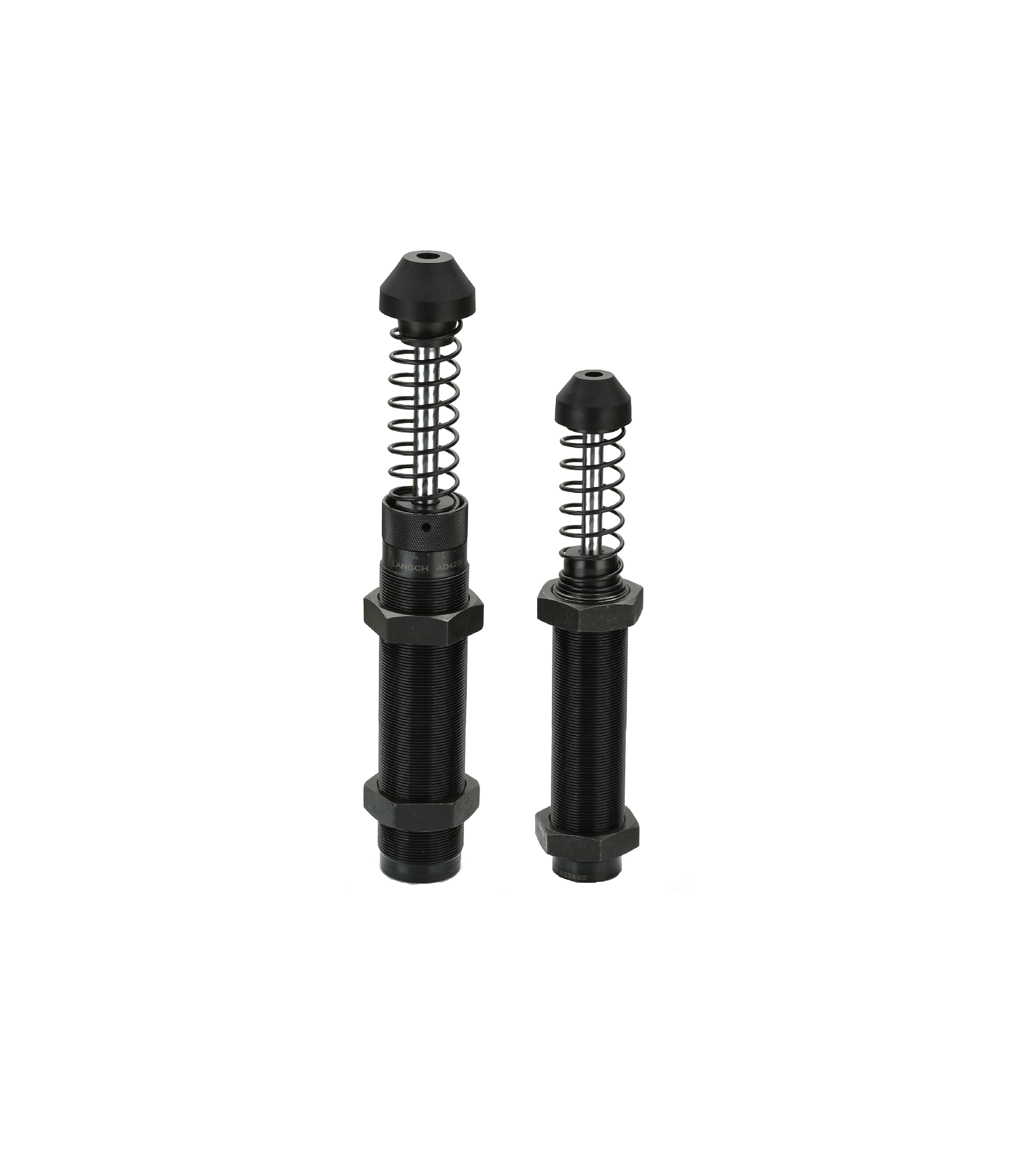
When shortlisting damping technologies, you must evaluate them through specific performance lenses. We look closely at the deceleration profile, the maximum cycle limits, and the overall load capacity. Understanding how different materials react to kinetic energy ensures you pick the right tool for the job.
Elastomer bumpers and heavy coil springs represent the entry-level tier. They are inexpensive, easy to mount, and require zero maintenance. However, they suffer from the "bounce back" effect. As mentioned earlier, springs store energy. When a payload hits a rubber bumper, the bumper compresses and immediately pushes the load backward. This secondary vibration disrupts optical inspection cameras and destabilizes delicate payloads. You should only use springs for low-speed, non-critical applications where bouncing is acceptable.
A pneumatic shock absorber (often seen as air cushions built into air cylinders) offers a step up in performance. These devices trap a pocket of air and use it to slow down the moving mass. Because air is a compressible gas, pneumatic options create a non-linear, "spongy" deceleration curve. The resistance feels soft at first and ramps up aggressively at the end of the stroke. They work exceptionally well for light loads in cleanroom environments where you cannot risk oil leaks. However, at high impact velocities, the compressible nature of air makes the payload prone to bouncing. They struggle to manage heavy, high-speed impacts effectively.
Hydraulic industrial shock absorbers remain the gold standard for automation. They rely on the incompressible nature of specialized hydraulic fluid. When you force oil through a metered orifice, it behaves predictably every single time. This incompressible trait is an absolute requirement for achieving high-precision, heavy-load, true linear deceleration without any bounce back.
| Technology Type | Deceleration Profile | Energy Handling | Best Application Scenario |
|---|---|---|---|
| Elastomer Bumpers | Non-linear (High Rebound) | Stores energy temporarily | Low-speed, low-cost mechanical stops. |
| Pneumatic Cushions | Non-linear (Spongy) | Compresses gas to absorb impact | Light payloads, cleanroom environments. |
| Hydraulic Absorbers | Linear (Zero Rebound) | Converts kinetic energy to heat | High-speed automation, varying payloads. |
You cannot select a shock absorber by merely matching the thread size to a mounting bracket. Proper specification requires precise mathematical calculations to determine the exact energy handling requirements. If you guess the load parameters, you risk destroying the shock on its first cycle. Engineers must calculate four critical metrics.
First, determine the total mass moving into the shock. This includes the product, the carriage, and any fixtures. Second, calculate the impact velocity at the exact moment of contact. Since kinetic energy squares the velocity, a small increase in speed creates a massive increase in impact energy. Third, you must account for the propelling driving force. If an electrical motor or a pneumatic cylinder continues pushing the load while it hits the shock, this additional motor force adds to the total energy. You combine the impact mass and the propelling force to find the "effective weight." Finally, track the expected cycles per hour. Frequent impacts generate heat. You must ensure the unit can dissipate this heat fast enough.
When you scale up to massive applications like overhead bridge cranes or heavy foundry equipment, standard units fail quickly. A proper heavy duty industrial shock absorber incorporates specific upgrades. Extreme loads require much larger oil capacities to absorb the immense thermal energy. Some models utilize external hydraulic accumulators to handle the displaced fluid. Furthermore, you might need specific shock body materials. Corrosive foundry environments or washdown food processing plants often require solid stainless steel bodies to prevent rapid rust and degradation.
Do not ignore compliance and standardization during your evaluation. Verify that the unit meets global ISO standards and RoHS compliance, especially if you export your machinery internationally. Always prioritize vendors that provide comprehensive 3D CAD downloads. Integrating the exact shock model into your machine design software before purchasing prevents costly mounting interference issues later on the assembly floor.
Even the most accurately specified shock absorber will fail if you install it poorly. Side-loading stands out as the most common installation pitfall. Engineers design shock absorbers to handle purely axial loads, meaning the payload must strike the piston rod perfectly straight on. If the load hits at an angle, it bends the rod slightly. This off-center impact scrapes the delicate rod seals against the inner bearing. The seals tear prematurely, hydraulic fluid leaks out, and the shock loses all damping capability. If your machine geometry forces an angled impact, you must install a side-load adapter. These heavy-duty collars protect the piston rod from lateral stress.
Thermal overload represents another hidden implementation risk. Every shock absorber carries a maximum energy capacity rating per hour (Nm/hr). This rating dictates how much heat the unit can shed into the surrounding air. If your cycle rates exceed this limit, the heat builds up rapidly. The hydraulic fluid literally boils inside the pressure tube. Boiling fluid expands, ruptures the seals, and destroys the component. You must verify ambient temperatures during your design phase.
When you begin shortlisting vendors, use a logical filtering process. Look for manufacturers that offer extensive CAD libraries and transparent, easy-to-use sizing calculators on their websites. A vendor with local technical distributor support provides a massive advantage. If you run into tuning issues during a weekend commissioning phase, having a local application engineer to call can save your project timeline.
Controlling deceleration is not an optional upgrade; it is a mathematical necessity for protecting vital capital equipment. Allowing unmanaged kinetic energy to batter your machinery guarantees early mechanical failure and unacceptable downtime. Upgrading your end-of-stroke damping fundamentally changes how smoothly your automated processes run.
An adjustable model offers the safest path forward for most engineers. It mitigates the risk of slightly inaccurate initial calculations. More importantly, it seamlessly adapts to future production changes, whether you decide to increase line speeds or process heavier product variations on the same machine.
Do not leave your machinery vulnerable to impact damage. Download an online sizing calculator today, input your specific mass and velocity numbers, and access the corresponding CAD models. Consult with a qualified application engineer to verify your effective weight calculations before finalizing your automation design.
A: You adjust it using a numbered dial or screw mechanism located at the rear or front of the unit. Start by setting the dial to a medium resistance. Run the machine at a very low speed. Observe the impact. If the load bounces, the setting is too hard. If it violently bottoms out, the setting is too soft. Gradually tweak the dial and slowly increase the machine speed until you achieve a smooth, silent stop with no bouncing or crashing.
A: A dashpot primarily provides velocity control. It resists motion linearly to maintain a steady, slow speed, often used in lids or precise mechanisms. An industrial shock absorber focuses entirely on impact energy absorption. It takes the kinetic energy of a fast-moving, heavy mass and safely dissipates it as heat over a short stroke, stopping the load completely.
A: You should replace it immediately if you spot clear failure symptoms. The most obvious sign is visible hydraulic oil pooling around the piston rod or dripping down the mounting bracket. Audible symptoms include loud metallic banging, indicating the internal fluid has leaked and the unit is bottoming out. You might also notice increased structural machine vibration during the end-of-stroke impact.

