
Views: 0 Author: Site Editor Publish Time: 2026-09-02 Origin: Site


Automation faces a core conflict in modern manufacturing. The relentless drive for faster cycle times directly increases kinetic energy. This uncontrolled energy severely threatens capital equipment longevity. Standard commercial damping differs vastly from continuous-duty automation. Robotics, high-speed conveyors, and precision assembly lines require robust solutions. They operate constantly and cannot afford unexpected downtime.
Properly specified Industrial Shock Absorber units solve this exact conflict. They reliably convert damaging kinetic energy into thermal energy. This critical conversion enables maximum throughput across your facility. It achieves high speeds without compromising machine structural integrity or precision. You will learn how to manage kinetic energy effectively. We will explore core mechanics and component selection. Finally, you will discover how to avoid common implementation risks.
High-speed automation generates severe impact forces. These extreme forces occur at the end of every stroke or cycle. You cannot ignore them without facing severe consequences. Moving heavy payloads at high velocities creates massive kinetic energy. This energy must go somewhere when the motion stops.
Many engineers try basic alternatives first. They often install standard rubber bumpers, steel springs, or basic cylinder cushions. These options fall drastically short in automated environments. Rubber bumpers and springs simply store kinetic energy temporarily. They do not dissipate it. This causes a violent "bounce back" effect. The stored energy returns directly into your expensive machinery.
The cost of inaction piles up quickly. Unmanaged impacts create cascading failures across the factory floor. You will experience vibration-induced sensor faults. You might find cracked mounting brackets on robotic arms. Maintenance downtime increases rapidly as components fail prematurely. Degraded product quality often follows as precision alignment drifts.
You need a highly successful mitigation strategy. A proper solution achieves smooth, linear deceleration every single time. Elastic rebound must drop to absolute zero. This approach maximizes the lifecycle of your automated cell. It protects your sensors, tooling, and structural frames.
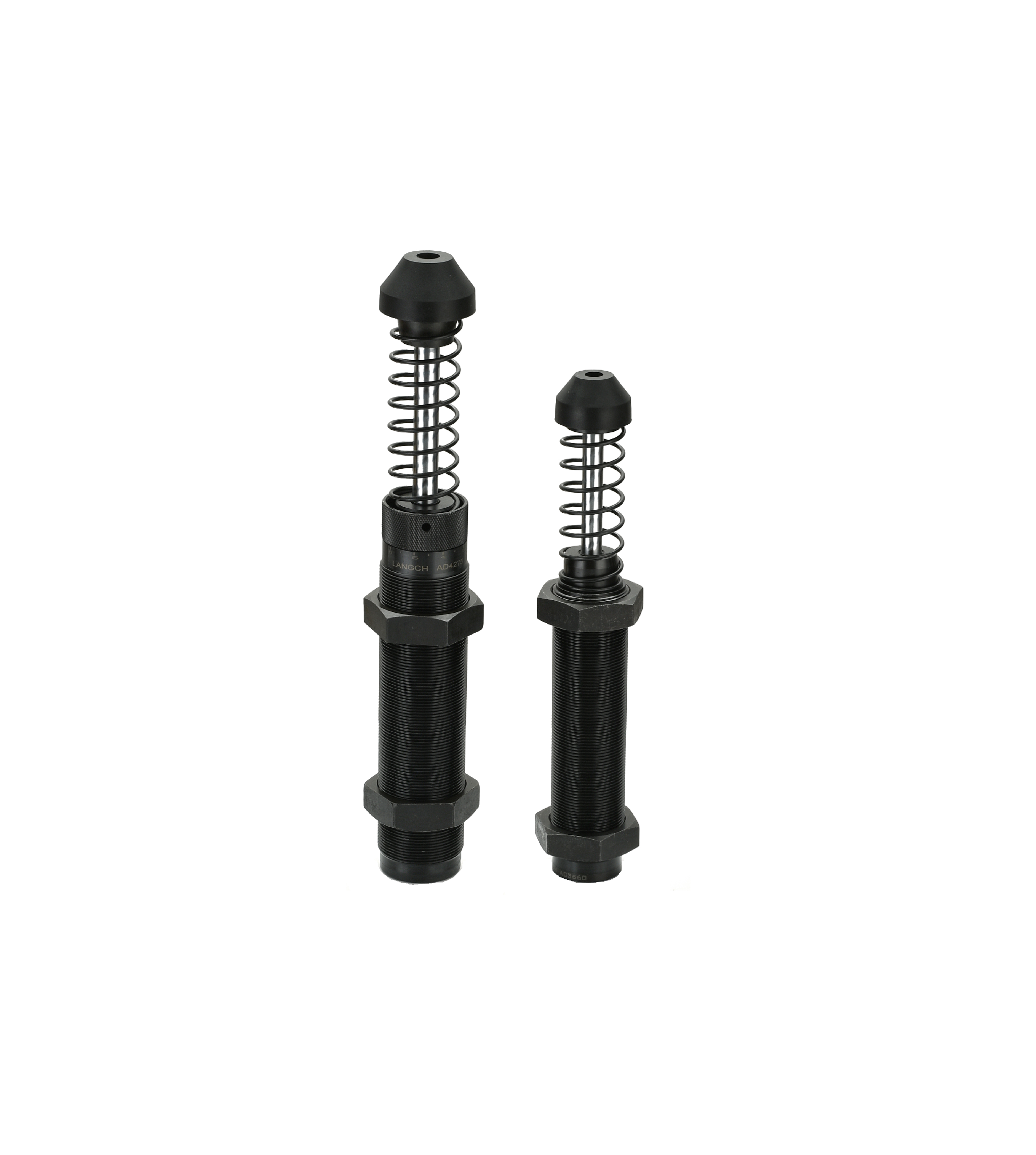
You must understand the underlying principle of energy management. The process relies on direct energy conversion. The unit changes kinetic energy into fluid friction. This fluid friction immediately becomes thermal energy. The system then dissipates this heat into the surrounding air.
The orifice metering system drives this entire process. An internal piston pushes hydraulic fluid through precisely engineered orifices. As the payload slows down, the fluid flow changes. This action maintains constant resistance throughout the entire stroke. It perfectly matches the deceleration curve.
Linear deceleration remains the ultimate engineering goal. Contrast a high-quality industrial shock absorber damper against non-metered dampers. Non-metered units create dangerous, jagged peak-force curves. These sudden spikes damage equipment instantly. Metered units provide a safe, completely flat deceleration curve. The stopping force remains steady from start to finish.
Thermal dissipation requirements matter immensely. The ability to shed heat is absolutely critical. It is just as important as stopping the physical load. This applies heavily in high-cycle automation environments. If a unit cannot shed heat, the internal fluid boils. The seals will eventually rupture.
You face several choices when selecting a deceleration component. Let us break down the primary categories. Understanding these differences prevents catastrophic design failures.
Self-compensating models feature a fixed internal orifice design. They work best for predictable, unchanging loads. We recommend them for strict, tamper-proof environments. Factory operators cannot accidentally alter their settings.
Adjustable models offer more flexibility. They feature an external dial to change orifice flow. A reliable adjustable industrial shock absorber suits multi-product lines perfectly. They handle fluctuating load weights and changing velocities with ease. You just turn the dial to match the new line speed.
Some industrial applications demand massive energy capacities. Think of overhead gantry cranes or heavy foundry equipment. Large-scale automated warehousing also requires immense stopping power. A heavy duty industrial shock absorber fits here. These components boast much larger bore sizes. They feature incredibly robust outer bodies to survive harsh impacts.
Sometimes you absolutely cannot use hydraulic fluid. Medical device manufacturing or semiconductor cleanrooms view fluid leaks as catastrophic. A pneumatic shock absorber uses compressed air instead. This provides a remarkably clean, safe alternative. If they vent, they only release clean air into the environment.
Shock Absorber Category Comparison
| Category Type | Primary Advantage | Ideal Application Scenario | Maintenance Need |
|---|---|---|---|
| Self-Compensating | Tamper-proof, fixed performance | Dedicated assembly lines, constant loads | Low |
| Adjustable | Tunable damping force | Multi-product lines, prototyping | Medium (Verification) |
| Heavy Duty | Massive energy capacity | Gantry cranes, foundry equipment | Medium (Visual checks) |
| Pneumatic | Zero hydraulic fluid risk | Medical cleanrooms, semiconductors | Low |
You must evaluate specific mathematical dimensions for automated systems. Precision calculation ensures long-term reliability. Guesswork leads directly to broken machinery.
This remains the most critical set of calculations. You must balance the sheer stopping power required (E3). You must also respect the thermal limits of continuous operation (E4). Continuous operation generates significant internal heat. If E4 exceeds the unit's rating, it will fail rapidly.
Do not just look at the static mass. You must factor in the propelling force. Pneumatic or electric actuators actively drive the load forward. This pushing force adds immense energy to the impact. The shock absorber must stop the mass and fight the actuator simultaneously.
Assess your exact operating environment carefully. Do you need stainless steel outer bodies? Do you require specialized rod wipers? Food-grade fluids might be necessary for washdown areas. Extreme heat or abrasive dust also dictate your material choices.
Evaluate available thread sizes and required stroke lengths. You must integrate physical stop collars. Stop collars prevent the internal piston from bottoming out violently. Space constraints often dictate whether you use a long-stroke or short-stroke model.
Real-world implementation brings specific mechanical risks. You must prepare for them during the design phase.
Angular impact causes rapid, premature failure. It remains the most common field issue. You must use specialized side-load adapters if angles exist. Strict mechanical alignment is absolutely mandatory. Keep the impact trajectory within 1-2 degrees of the central axis. Excessive side-load snaps the piston rod or ruins the pressure seal.
We mentioned this earlier, but it deserves deep emphasis. Calculating requirements based on mass alone is highly risky. You must include the active driving force. A pneumatic cylinder pushing a 10kg load adds significant kinetic energy. Ignoring this force destroys the damper in hours.
You need positive mechanical stops. Engineers typically call these stop collars. They prevent the shock absorber from acting as the final mechanical stop. The piston should never hit the bottom of the internal tube. The stop collar takes the final resting force safely.
Assess dynamic seal wear transparently. Hydraulic fluid breaks down over millions of cycles. You must plan for preventative maintenance. Monitor the deceleration profile over time. If the load starts bouncing, the internal seals have likely degraded.
Your procurement process needs a logical, step-by-step flow. Follow these specific steps carefully to ensure success.
Industrial shock absorbers are not mere optional accessories. They act as foundational mechanical components. They directly dictate the maximum safe speed limit of your automated system. Without them, you must run your equipment at inefficiently slow speeds.
Careful mathematical sizing upfront saves massive amounts of money. It prevents costly structural failures downstream. It eliminates the risk of smashed sensors and broken robot joints. Take the time to calculate E3, E4, and effective weight accurately.
Take action on your automation design today. Download a dedicated sizing calculation worksheet. View our comprehensive product specification tables online. Contact an experienced application engineer if you need help with complex integrations. Protect your machinery and maximize your throughput now.
A: Dashpots provide basic velocity control. They usually handle lower forces and maintain a constant speed. Shock absorbers operate differently. They are specifically designed to safely decelerate a heavy moving mass to a complete, dead stop.
A: They can definitely be used permanently. However, they carry a slight risk of unauthorized tampering on the factory floor. They are highly recommended when frequent line changeovers require different damping profiles.
A: Point to three likely engineering faults. You might have excessive side-loading bending the rod. You might be exceeding maximum cycle rates, which overheats the seals. Finally, you might lack an external mechanical stop collar.

