
Views: 0 Author: Site Editor Publish Time: 2026-09-23 Origin: Site


Industrial automation systems face a continuous tradeoff between cycle speed and equipment longevity. You want higher throughput, but you also need machines to last. When operating parameters fluctuate, standard fixed-orifice dampers often fail. Load weights change between batches. Impact velocities vary based on driving forces. These variations prevent fixed dampers from providing consistent deceleration.
This inconsistency leads directly to structural fatigue. It can also bottleneck your overall production throughput. For engineers and procurement teams, evaluating deceleration components is critical. Choosing an adjustable unit requires weighing upfront costs against operational flexibility. This guide outlines the precise mechanical and business conditions justifying the specification of an adjustable industrial shock absorber. We will explore energy calculations, heavy-duty applications, and vital installation protocols.
Engineers must first understand the baseline mechanics of traditional fixed damping. Manufacturers calibrate a fixed industrial shock absorber for a single, unchanging mass and velocity. They drill specific orifice holes inside the pressure tube. These holes restrict fluid flow at a predetermined rate. As the piston rod compresses, the fluid escapes through these orifices. This action converts kinetic energy into thermal energy. If the mass and speed remain constant, the deceleration curve stays perfectly smooth.
However, automation environments rarely remain static. Miscalculating these parameters carries heavy mechanical consequences. Imagine running a packaging line handling 10-kilogram boxes. You suddenly switch to running 25-kilogram boxes. A fixed shock absorber tuned for the lighter load will fail to slow the heavier mass. The piston rod will crash into the end of its stroke. This creates a severe mechanical spike. We call this "bottoming out." The resulting shockwaves travel through the machine frame. They cause excessive noise, loosen fasteners, and damage sensitive sensors.
Conversely, if a lighter load hits a shock absorber tuned for a heavy mass, the fluid resistance is too high. The load bounces off the piston rod. This abrupt stop causes similar structural stress. It also ruins positional accuracy for downstream processes.
You should specify an adjustable model in several distinct scenarios. First, look at applications requiring frequent product changeovers. Packaging lines, robotic sorting cells, and material handling conveyors often see shifting weights. Second, consider systems displaying inconsistent friction. Pneumatic cylinders often experience pressure fluctuations. These fluctuations change the final driving force. Exact velocities become difficult to calculate precisely during the CAD design phase.
Finally, adjustable models excel in rapid prototyping. Engineering teams often prioritize fine-tuning in the field over theoretical modeling. You can install an adjustable unit, run the machine, and dial in the perfect deceleration curve manually. This saves countless hours of mathematical simulation.
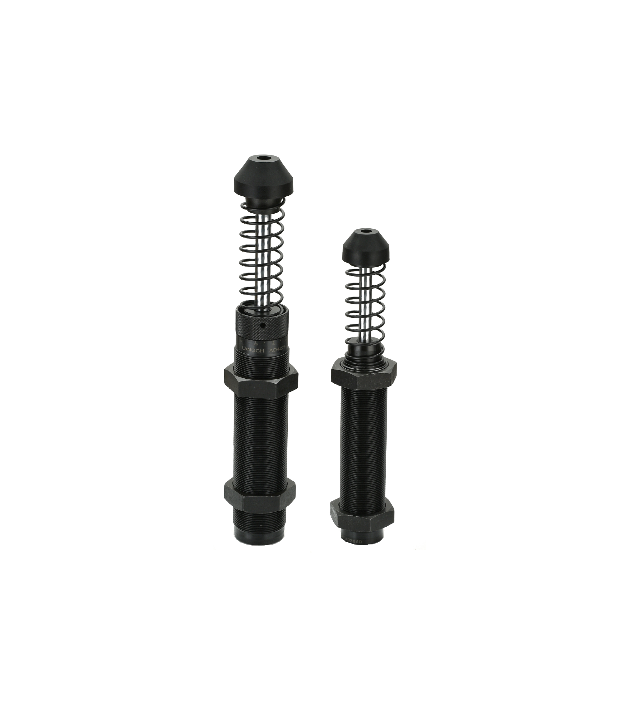
Selecting the right deceleration component moves far beyond basic physical dimensions. Engineers must adopt a formulaic approach to energy capacity and sizing. You must calculate two critical metrics before choosing any unit.
First, evaluate the required energy per cycle, measured in Newton-meters per cycle (Nm/cycle). This metric represents the kinetic energy of the moving mass upon impact. You calculate this using the mass and impact velocity. You must also add the propelling force acting on the mass during deceleration. Second, evaluate the energy per hour (Nm/h). You calculate this by multiplying the energy per cycle by the number of cycles per hour. This second metric determines heat dissipation. If a shock absorber absorbs too much energy per hour, the internal hydraulic fluid boils. The seals degrade. The unit fails prematurely.
Understanding how specific design features translate to operational outcomes helps justify procurement decisions. We map these features below.
Feature-to-Outcome Mapping for Adjustable Dampers| Design Feature | Mechanical Outcome | Operational Benefit |
|---|---|---|
| Multi-orifice variable tuning dial | Alters internal fluid flow pathways dynamically. | Achieves smooth, linear deceleration despite load shifts, reducing machine vibration. |
| High-tensile steel construction | Resists internal pressure spikes and external impacts. | Enhances structural integrity and reduces wear under high-cycle environments. |
| Hard-chrome plated piston rod | Minimizes friction against the rod seal during actuation. | Extends seal life and prevents premature hydraulic fluid leakage. |
| Integrated positive stop | Mechanically limits the final stroke travel distance. | Protects internal components from catastrophic bottom-out damage. |
Sizing also demands rigorous CAD integration. You must download accurate 3D CAD models from the manufacturer. Insert these models into your digital machine assembly. Verify the stroke length visually. Ensure adequate mounting space around the adjustment dial. You must also check for potential collision points during the full stroke travel. Finding a spatial interference in CAD is free. Finding one on the factory floor is expensive.
Finally, engineers must consider the damping medium. Traditional hydraulic adjustable units dominate the market due to high energy capacity. However, certain applications demand a different approach. Semiconductor manufacturing, medical device assembly, and food processing often require strict clean-room compliance. In these environments, hydraulic fluid leaks pose severe contamination risks. Here, a pneumatic shock absorber becomes highly preferable. These air-based dampers offer excellent adjustability for low-mass applications while eliminating fluid contamination entirely.
Not all adjustable dampers handle the same scale of abuse. You must understand what distinguishes a standard unit from a heavy-duty model. A heavy duty industrial shock absorber features significantly larger bore sizes. This increased internal volume holds more hydraulic fluid. More fluid means vastly enhanced heat dissipation capabilities. Heavy-duty models also feature reinforced mounting flanges, thicker piston rods, and specialized high-temperature seals.
You typically specify heavy-duty models for extreme industrial environments. Automated Storage and Retrieval Systems (ASRS) rely heavily on these units. In an ASRS warehouse, massive shuttles move pallets weighing thousands of kilograms. If a software error causes a runaway shuttle, the end-stop shock absorbers must arrest that massive kinetic energy safely. Overhead cranes and foundry equipment present similar challenges. In these high-mass, low-velocity impact scenarios, structural failure presents significant safety risks. A failed damper can cause a crane payload to swing violently. This violates compliance regulations and endangers personnel.
However, over-engineering carries its own hidden dangers. Engineering teams often assume bigger is inherently better. They install a heavy-duty adjustable shock on a lightweight application, expecting maximum protection. This leads to a dangerous engineering reality known as the "brick wall" effect.
A heavy-duty damper requires substantial kinetic energy simply to overcome its initial internal seal friction and fluid resistance. If a small, fast-moving mass strikes an oversized damper, it lacks the energy to compress the piston rod. The shock absorber does not absorb energy. Instead, it acts like a solid steel rod. The light mass crashes into it and bounces off violently. This causes severe damage to the moving apparatus. Always match the damper's capacity range to the actual calculated energy. Do not upsize blindly.
Procuring the right component is only the first step. Proper field implementation dictates the actual lifespan of your equipment. The tuning process requires patience and systematic observation. You cannot simply guess the dial setting. Follow a logical, step-by-step approach to dial in the equipment safely.
Beyond tuning, mounting and alignment play critical roles in component longevity. You must align the shock absorber so the moving mass strikes it directly on its central axis. Off-center impacts cause severe side-loading. Side-load angles exceeding two or three degrees create immense leverage on the extended piston rod. This leverage bends the rod slightly during compression. A bent rod scrapes against the internal bearing. It quickly destroys the main hydraulic seal. If your application geometry forces an off-center impact, you must install side-load adapters. These mechanical guides absorb the lateral forces, allowing the piston to compress perfectly straight.
Operational risks also emerge post-commissioning. The primary risk involves unauthorized personnel tampering with the equipment. Operators often notice a machine running slightly out of rhythm. They might mistakenly twist the adjustment dial, hoping to "fix" the timing. This arbitrary adjustment ruins the engineered deceleration curve. It exposes the machine to immediate shock damage. To mitigate this risk, employ locking strategies. Most high-quality adjustable units feature a set screw or a mechanical lock nut. Once you achieve optimal deceleration during commissioning, tighten these locking mechanisms down. Treat the adjustment dial as a "set and forget" feature during normal production runs.
Even perfectly sized and flawlessly tuned components eventually wear out. You need an objective framework to determine the end-of-life for an industrial shock absorber damper. Relying on preventative maintenance schedules alone often leads to premature replacements or unexpected failures. Instead, train your maintenance teams to monitor specific physical wear indicators.
Conduct visual and auditory checks weekly. Look for these specific failure signs:
When you identify a failing unit, you must execute a strict replacement protocol. In many heavy-duty applications, engineers mount shock absorbers in parallel pairs. They do this to distribute massive kinetic energy loads evenly. If one damper fails, you might be tempted to replace only the broken unit. This is a critical engineering mistake.
You must replace shock absorbers in pairs. Over time, internal fluid degrades and orifices wear down, slightly altering the damping curve. A brand-new shock absorber performs very differently than a unit with three million cycles on it. If you pair a new damper with an old one, the new unit will absorb the vast majority of the kinetic energy. This unbalanced energy absorption creates catastrophic asymmetrical loading. The machine frame will twist upon impact. The new shock absorber will fail rapidly due to overloading. Always swap parallel units simultaneously to guarantee balanced deceleration.
An adjustable industrial shock absorber is not a universal fix for every automation challenge. Standard fixed units still hold value in highly predictable, single-load applications. However, adjustable damping remains the most mechanically sound choice for variable-load environments. It provides unmatched versatility during complex prototype testing. It allows your machinery to adapt to changing production demands without requiring physical component swap-outs.
Your engineering team should take immediate action. First, map out your production variables. Calculate your maximum energy per cycle and your worst-case energy per hour. Assess exactly how much your load weights and velocities fluctuate during normal operations. Next, select an appropriate energy capacity range and integrate preliminary CAD models into your digital assemblies to verify mounting clearances.
Do not leave these calculations to chance. Contact an application engineer today. Have an expert review your kinetic energy calculations. Request specific CAD downloads to ensure completely accurate system integration. Proper specification now prevents catastrophic machine downtime later.
A: Yes, provided they are specified with appropriate materials. You must select units featuring stainless steel construction and special food-grade or cleanroom-compliant seals. Alternatively, you can substitute a hydraulic unit with a cleanroom-compliant pneumatic shock absorber, which uses air to dissipate energy and entirely eliminates the risk of fluid leakage.
A: The optimal setting utilizes the entire available stroke length to decelerate the load smoothly. You want the moving mass to slow down gradually and come to a gentle rest just before hitting the mechanical end limit. If it bottoms out abruptly, the setting is too soft. If it stops too early, it is too stiff.
A: The damper will not compress properly. It acts like a solid barrier. The moving mass lacks the kinetic energy to overcome internal seal friction, causing it to bounce off the rod. This creates high-impact shockwaves through the machine structure. Proper initial sizing is required even for adjustable units.
A: No. Heavy-duty units come in both fixed-orifice and adjustable variations. Manufacturers often custom-machine fixed units for specific massive, unchanging loads. You only need an adjustable heavy-duty damper if that massive load frequently varies in overall weight or impact speed during normal operations.

